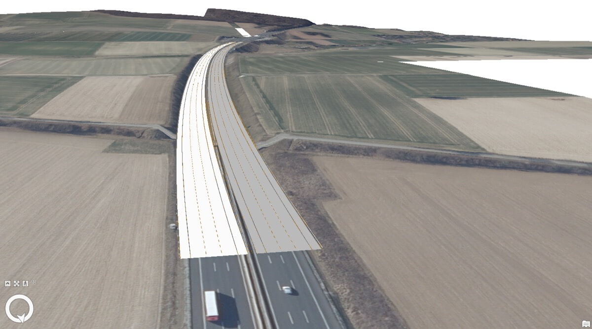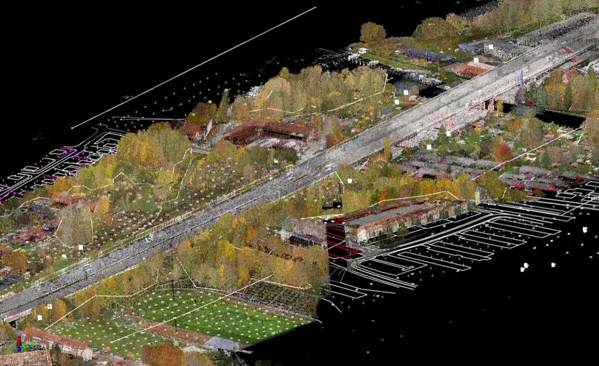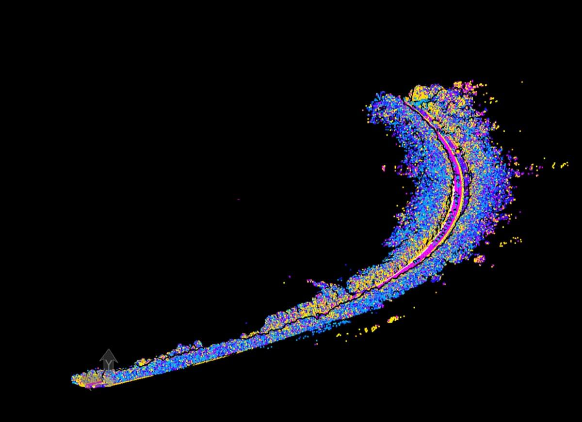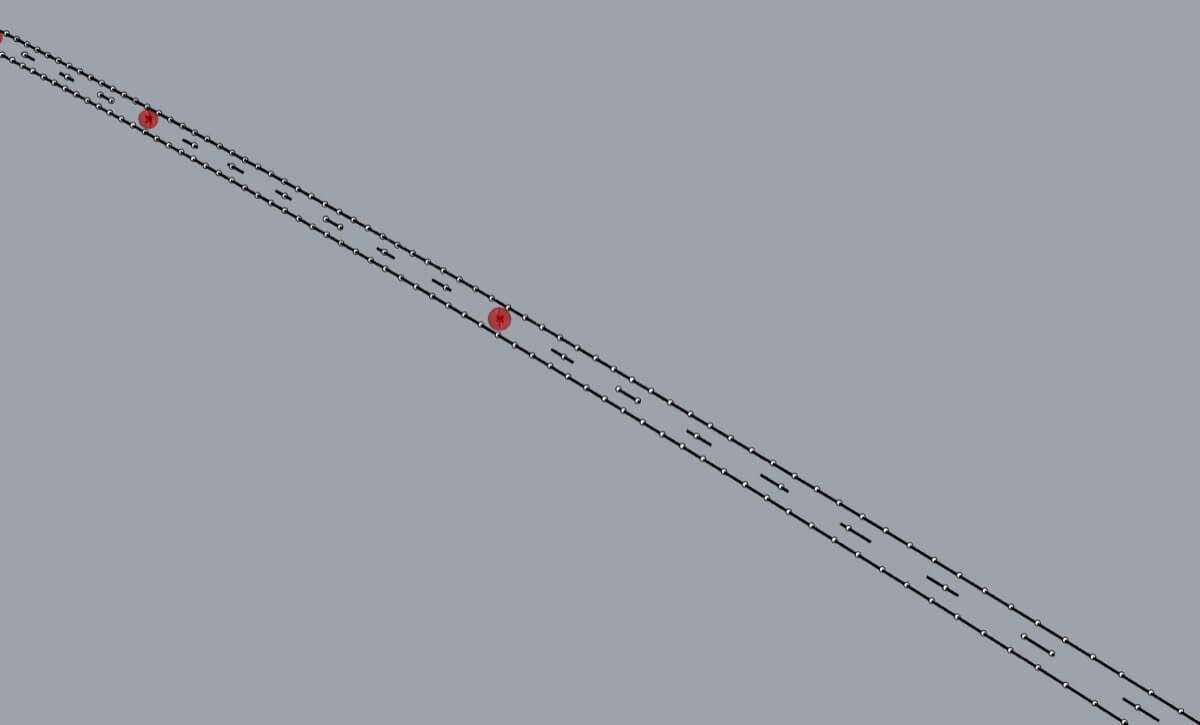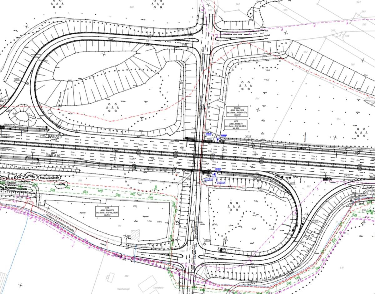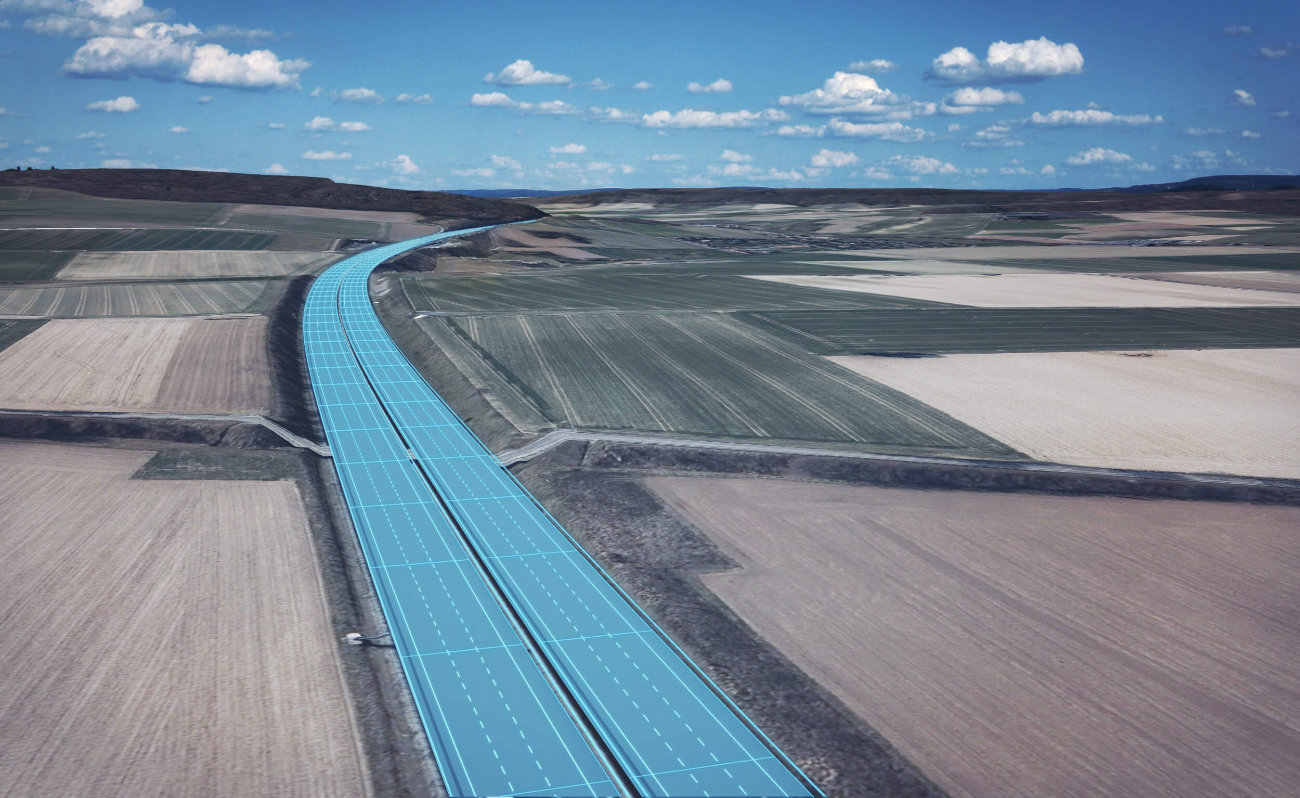
Three companies — Vermessungsbüro Rink GbR, Lang&Lang GmbH and ioLabs AG — have joined forces to revolutionize highway digitization by combining advanced 3D scanning, AI-driven processing and modular workflows. The project focuses on transforming thousands of kilometers of highway into accurate, data-rich 3D models. Using high-accuracy LiDAR scanning, automated point cloud processing, and feedback loops, the system produces CAD- and GIS-ready outputs with unprecedented efficiency and accuracy. This innovative approach minimizes manual intervention, enables seamless integration with industry-standard tools, and paves the way for smarter infrastructure management.
Precission
2-3 mm
Points scanned from highway are captured with great accuraccy that allows us to work in high precision
Efectivity increase
95%
Our target is 10 minutes per Km pace
Highway lenght
unlimited
Incremental processing allows us to divide long highways into processable sections, and therefore the processable length is virtually infinite
Vermessungsbüro Rink GbR, Lang&Lang GmbH and ioLabs AG share a passion for smart, effective solutions and have joined forces to improve existing workflows to make the production process faster and more accurate. The goal is to effectively process large amounts of data — thousands of kilometers of highway sections to be 3D scanned and documented — in the shortest possible time and to develop an innovative solution for digital data models of large linear structures.
Technical concept
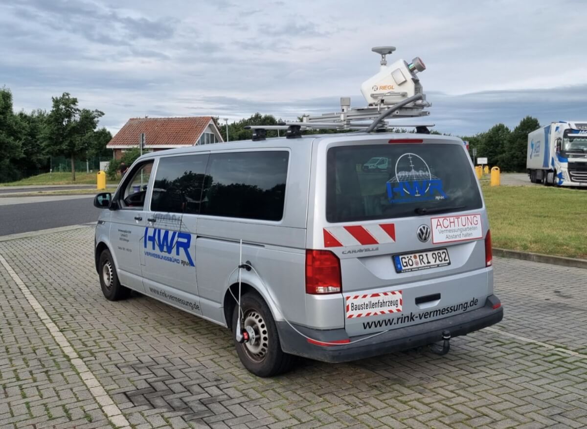
At the heart of this project, we are using advanced technologies that have great potential for automation. 3D scanners Riegl Vux 1Ha are capable of collecting large amounts of accurate, large-scale data. Combined with AI that can sort, process, and produce the data, it is possible to generate vector representations of highway objects in various data types.
Scanning
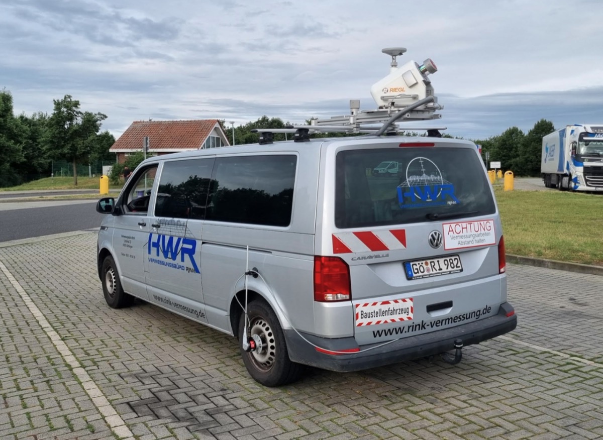
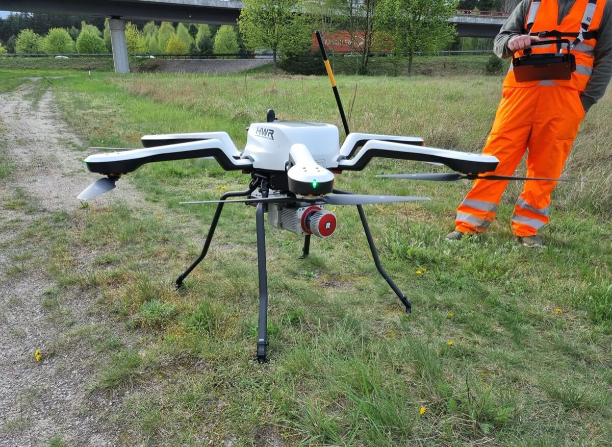
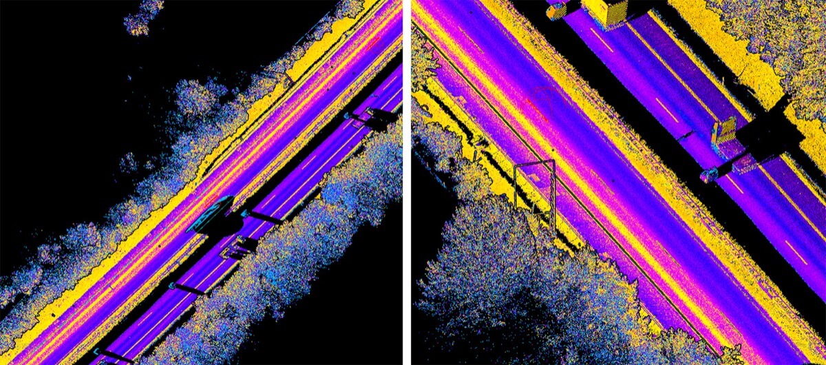
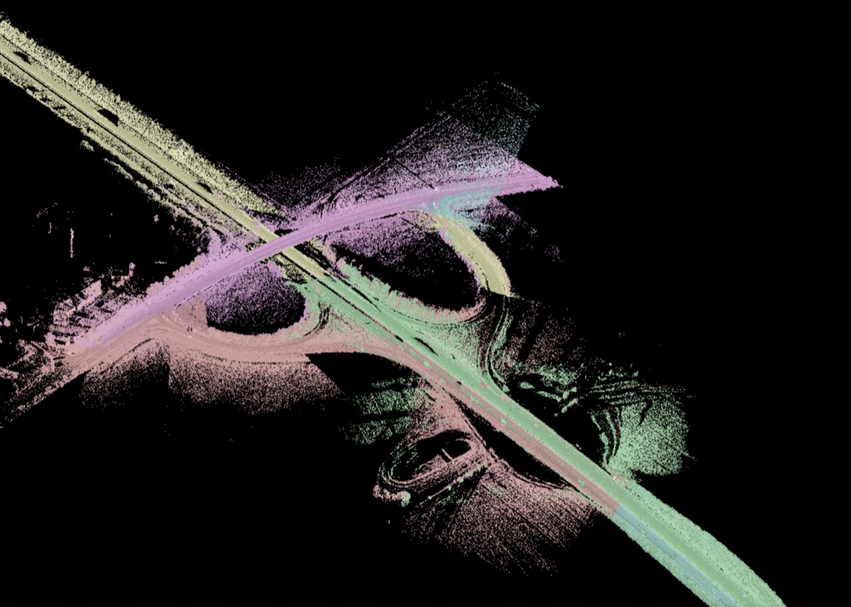
Car with the MLS system is used and during highway measurements it drives through every lane and side-line at +30 degrees and -30 degrees so that there are no gaps in the point cloud. The raw data is georeferenced using control points every 250 meters on both sides of the side line. In addition to the lanes, we usually make 2 flights per side. Car drone is used in combination with the drone scanner flights that scan large and not easily accessible areas. The scan data from the flight is georeferenced with the same control points as in the MLS system.
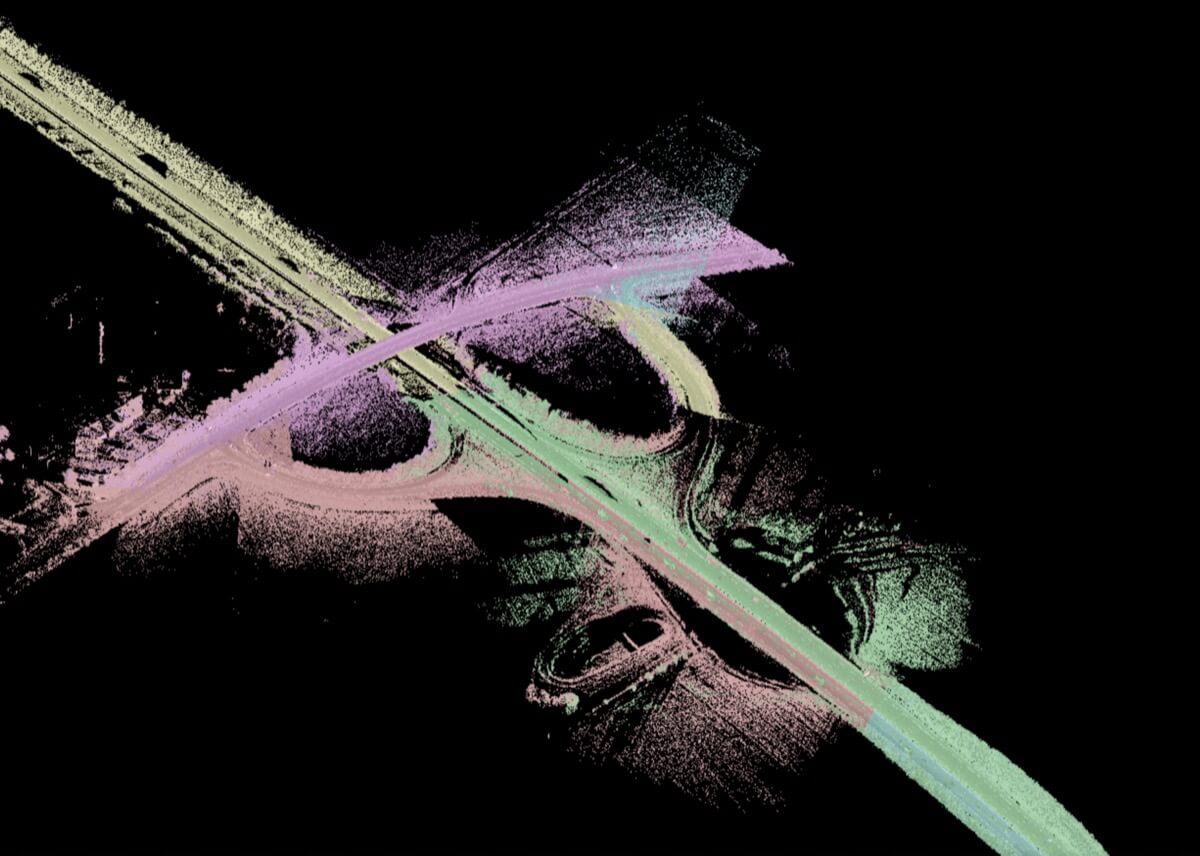
The scan result is a highly accurate set of point clouds in .las file type. By superimposing the scans, irrelevant, temporary obstacles (e.g. cars) are removed and shadow gaps caused by neighboring cars are filled. In this way we achieve the smallest possible deviations from the real object dimensions.
Automated pointcloud processing
The input of our tool is a point cloud. Module 1 takes the raw point cloud, filters irrelevant parts and identifies highway objects. The exchange file is the result of module 1 and contains mathematical models of highway objects in XML file. It serves as input for Module 2, which takes the exchange file and generates CAD models based on the mathematical definitions it contains. The result is a native model that has an accuracy of 90-95%. It also contains marked places where the imperfections were found. To further improve the Native model, Module 3 provides an opportunity to examine and correct problematic parts of the model. In this way, the final result, a 100% accurate native model, is achieved. Through a feedback loop, the problems found are fed back to Module 1, which implements the results of Module 3 and improves its processes for future data analysis.

Module 1
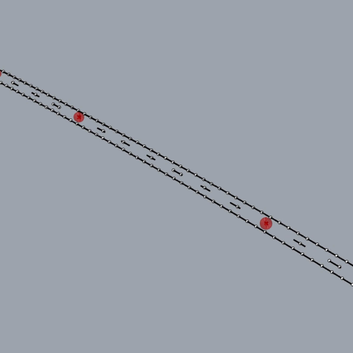
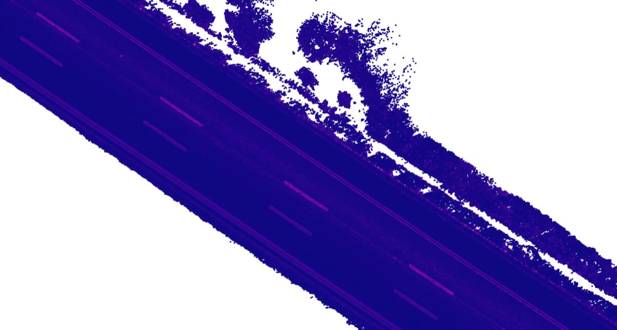
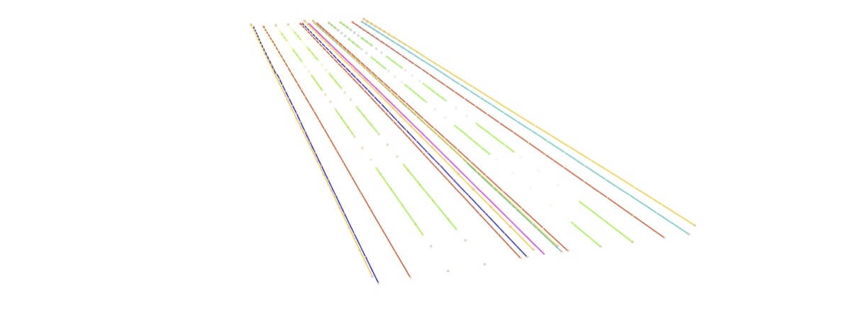
Module 1 focuses on analyzing point cloud data and creating a mathematical model of the geometry. This includes identifying and parameterizing features such as road edges, guardrails and their profiles, and road markings (center lines, edge lines). These elements are recognized as exact object types and precisely categorized.
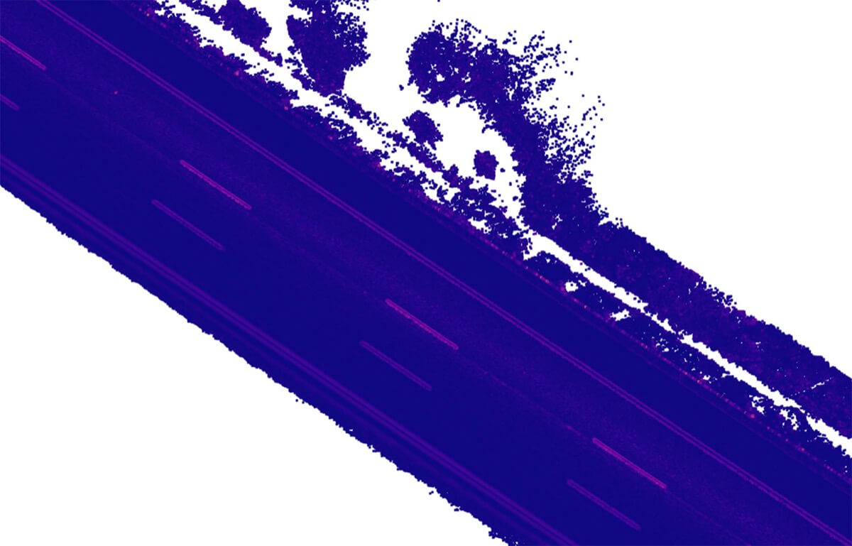
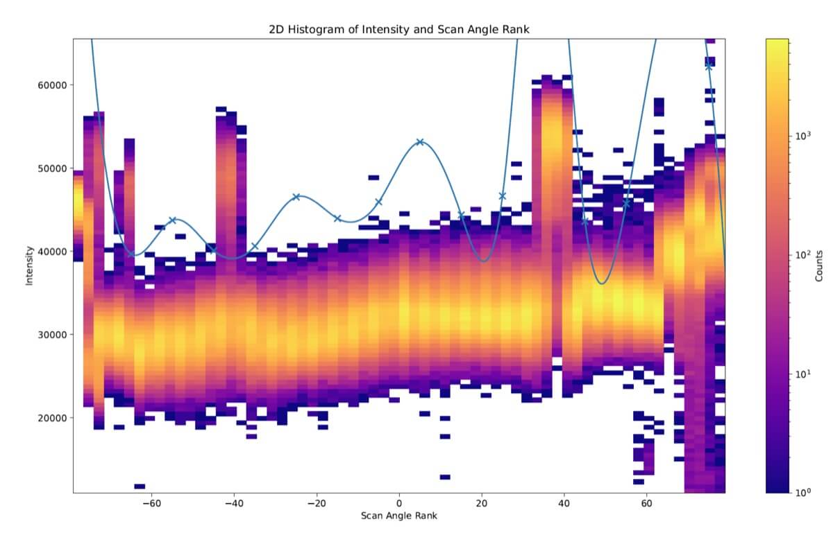
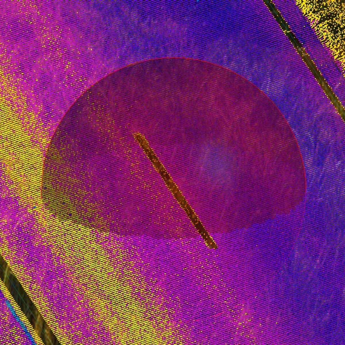
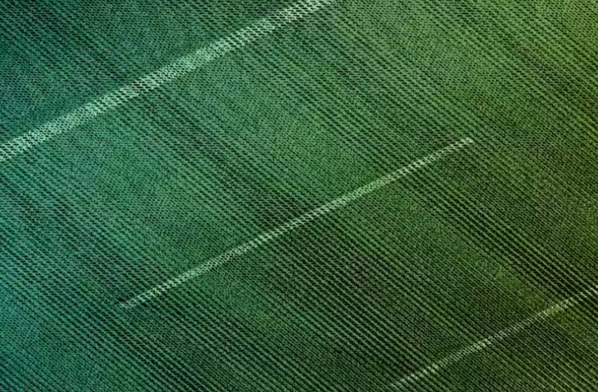
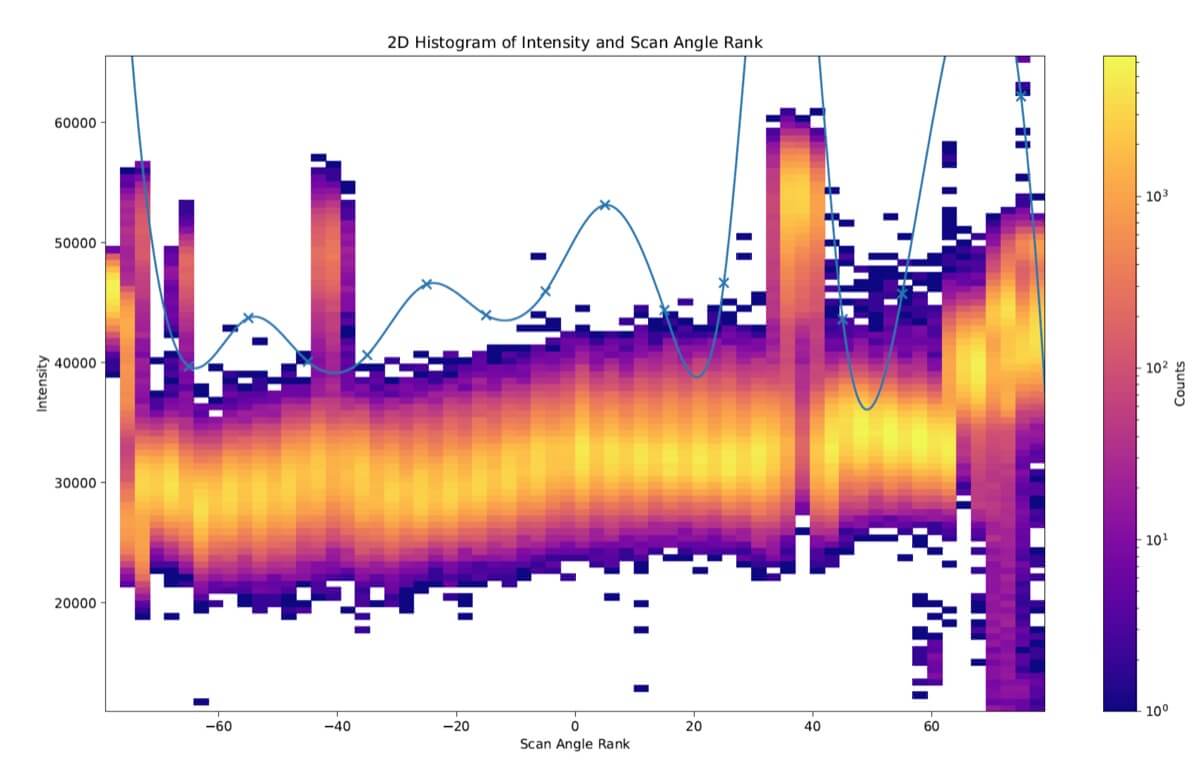
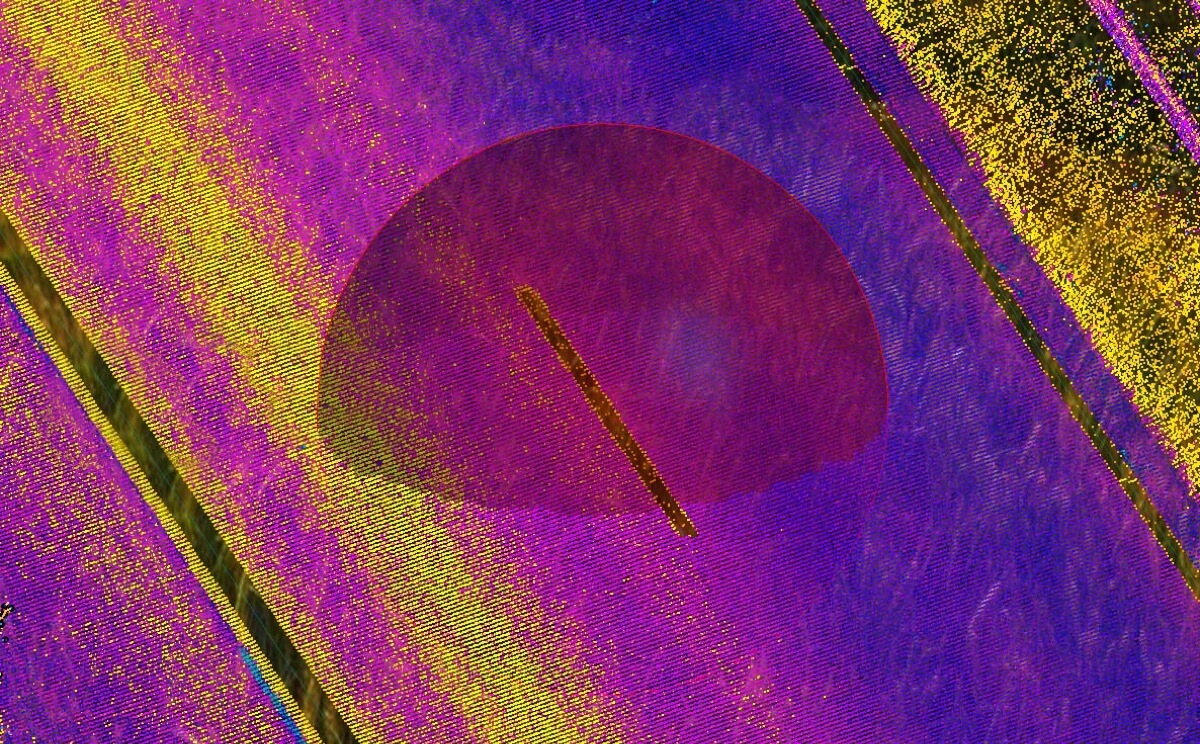
Module 1 performs several consecutive steps. At firts it is finding the highway ground plane, using the RANSAC algorithm and thus filtering relevant data. After that, points are selected by intensity. Road markings have higher reflectivity, compared to asphalt, and thus appear as brighter points in the LiDAR point clouds. We use peak analysis methods to separate bright line points within LiDAR angle-of-attack brackets.
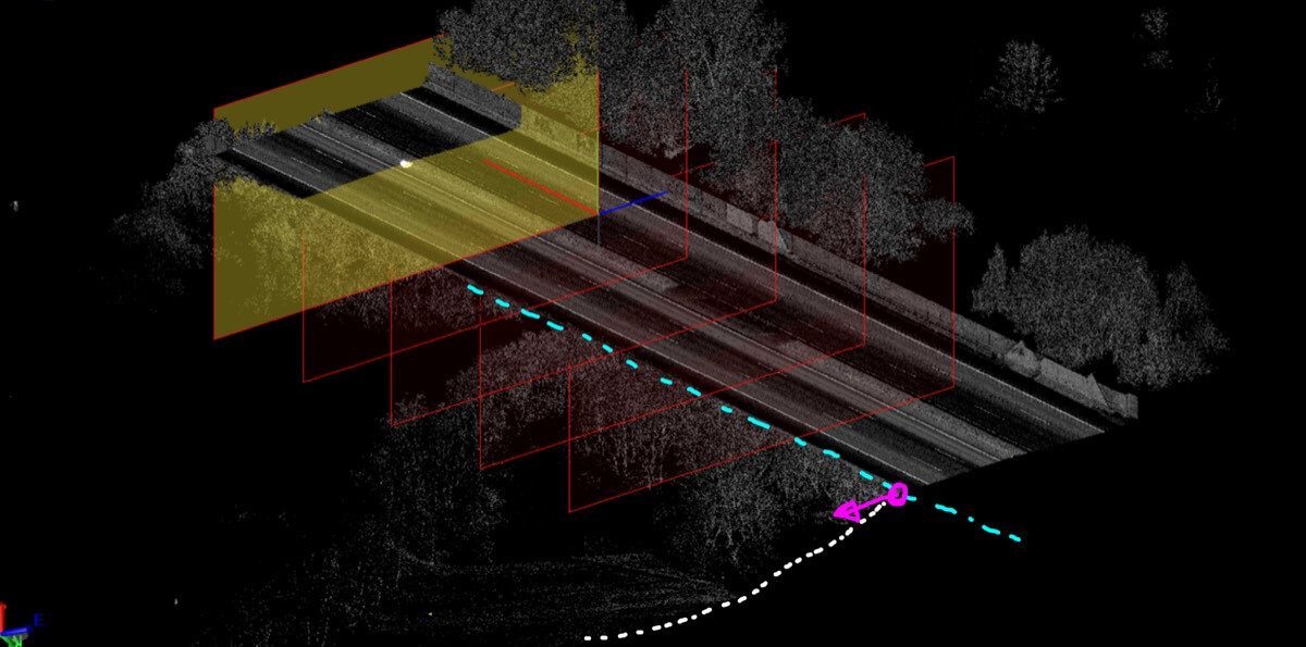
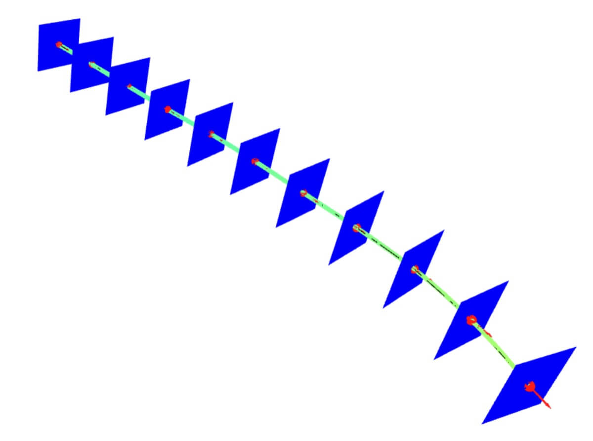
After those initial steps, it is nesessary to separate single objects. Clustering is performed – creating clusters of the highly reflective points using the DBSCAN algorithm. This separates each line into its own cluster. Machine learning is then used to recognize which clusters belong to road markings. Based on the lane clusters, objects are detected. Lines or other objects are fitted into splines and thus base for object vector representation is created. We use agent-based-modelling methods to model the lane shape. Shape are then refined – We find the precise edges of the detected objects to improve the accuracy of the rough shapes found in the previous steps. We use machine learning to detect guard rails within several cross-sections of the point cloud. We then fit the guard-rail shape to the detected positions. This locks the position of the guard rails precisely in 3D.
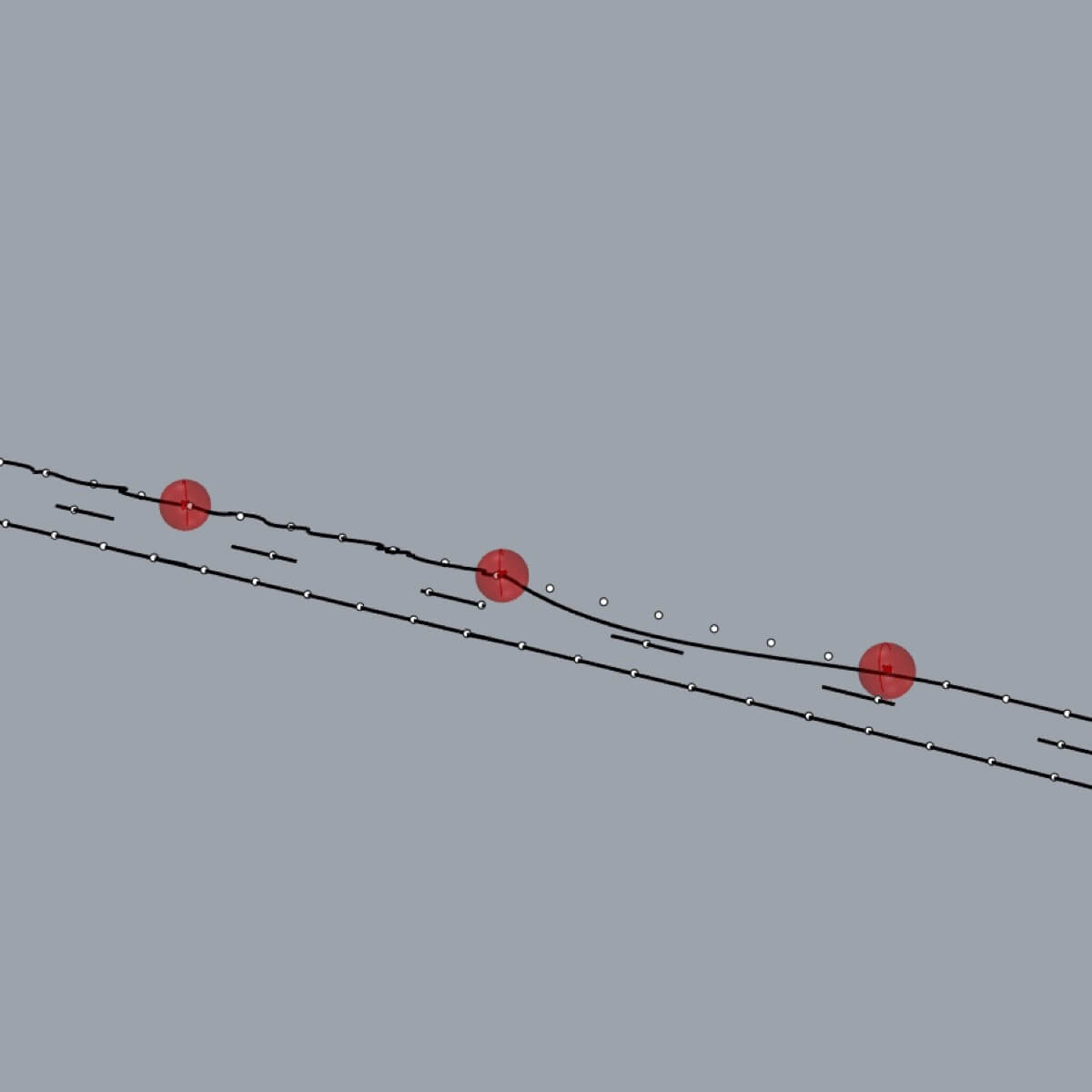
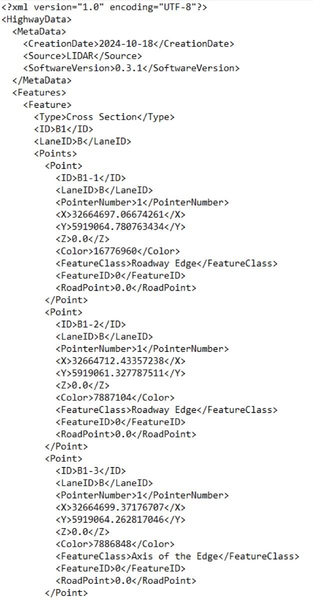
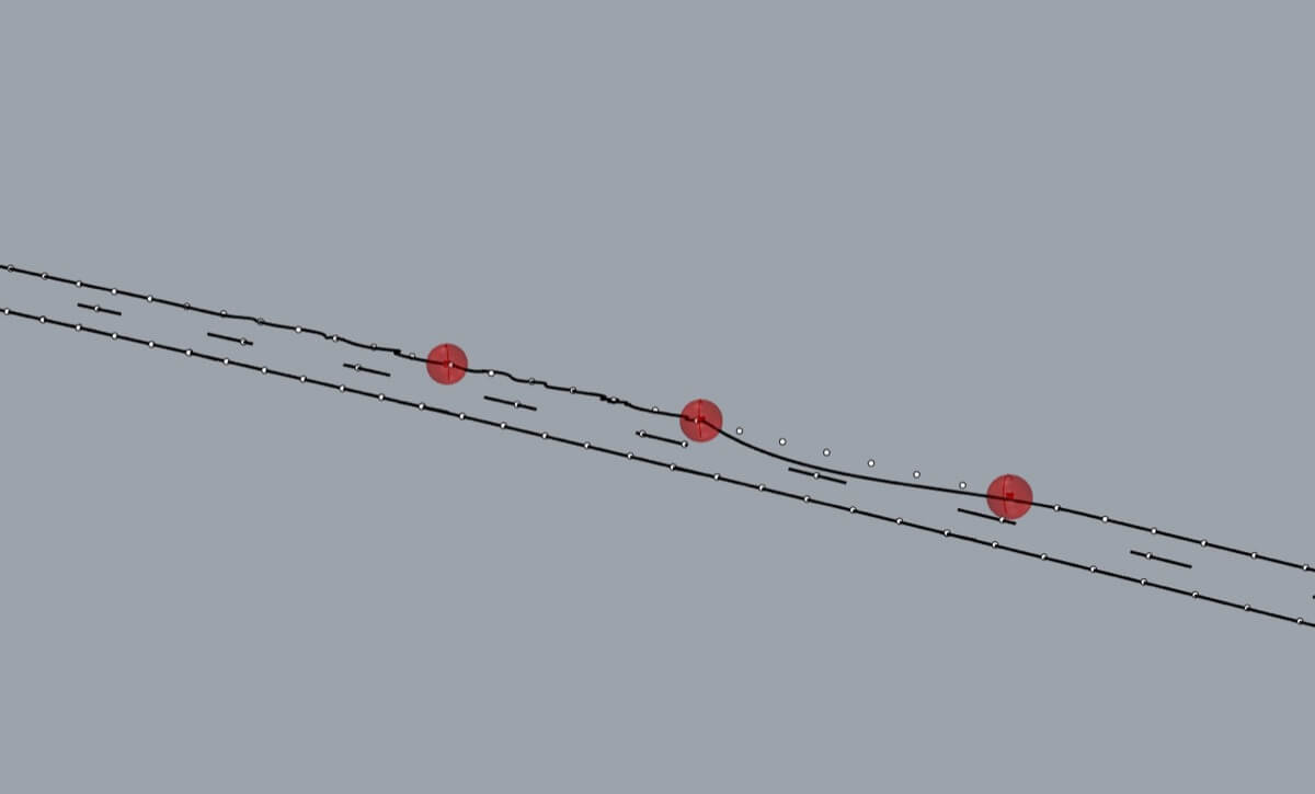
The processed data is formatted into an XML exchange file for easy interpretation by subsequent modules 2 and 3, with each element carrying geometric and semantic data. Module 1 also refines its output based on feedback from Module 3. Model parts that cannot be identified with sufficient confidence are marked in the exchange file so that they can be visually marked, for example, with a red, programmatically placed sphere at the problematic locations. This visual indicator will highlight areas that require further attention, allowing Module 3 to take over and focus more intensively on those specific sections.
Exchange file
The exchange file, generated by Module 1, facilitates seamless communication with Module 2. We use the XML format for its universal applicability, clarity, and ease of production, organizing the geometric and semantic data of each detected feature in a hierarchical structure that Module 2 can easily read, process, and understand.
Module 2
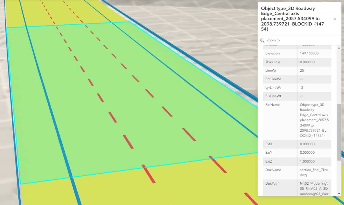
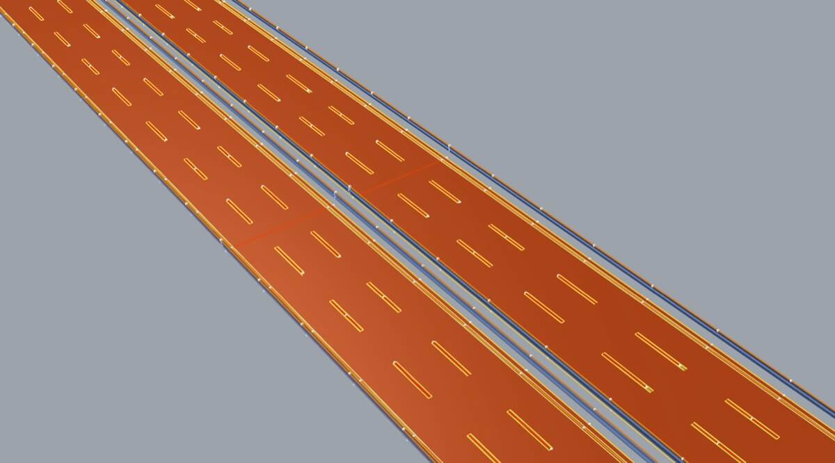
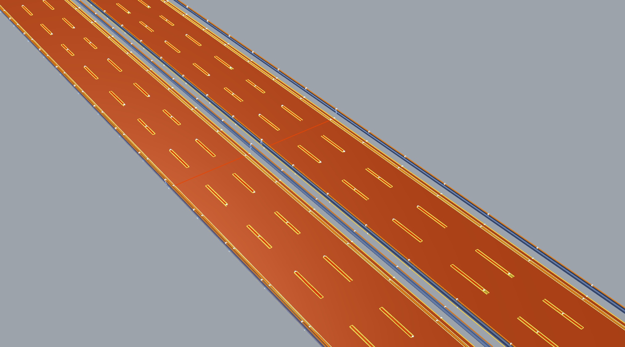
Module 2 focuses on processing the exchange file to create vector geometry and 3D models in native authoring software (such as Autodesk Revit Rhinoceros 3D or ESRI tools). These models represent the desired elements and are then exported in a format such as DWG or IFC, enriched with metadata for each individual component.
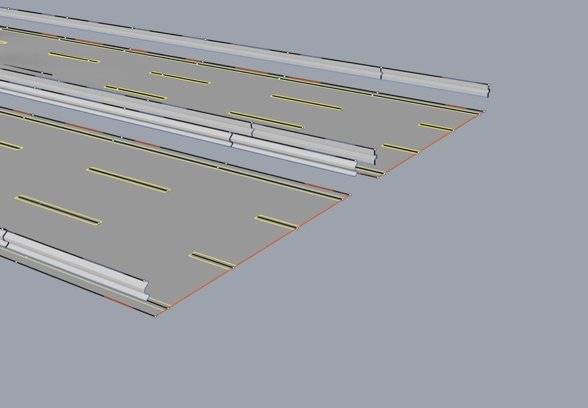
When the exchange file is loaded, the data is first sorted by geometry type. The geometry is then reconstructed into actual CAD elements. First, linear elements are processed and populated with the desired metadata. These elements are the first part of the result, but they also serve as the basis for more complex, three-dimensional surface elements that can further extend the range of highway representation. Generated 3D surfaces represent the road surface, crash barriers, or road markings.
The result of Module 2 is a CAD file that is fully compatible with various CAD and GIS formats and software.
Module 3
This module is dedicated to manual refinement of the result model, targeting gaps that automated processes may have missed and that need to be reviewed and possibly corrected by human workers.
This module 3 starts with a native CAD model that contains identified gaps. These gaps are visually marked for ease of use, allowing users to manually add, adjust or complete missing or inaccurate elements. This hands-on approach, combined with an automatic feedback loop, improves the accuracy of the previous modules, especially Module 1.
The final output is a fully comprehensive, error-free CAD model, with each element carrying geometric and semantic data. The resulting model is compatible with various CAD and GIS formats and software.
A key feature of Module 3 is its dynamic feedback loop. When a user manually edits a Module 2 result (such as a missing road marker), the system automatically updates and improves its model building workflow. This enables Module 3 to better recognize objects in future processes, thereby increasing its accuracy. This continuous learning process increases accuracy and minimizes manual adjustments over time, allowing the system to become more efficient and self-improving with each use.
We spend some time identifying use cases where AI can significantly accelerate the process of geometric model creation and refinement. While the primary goal of the tool is not to fully implement these AI solutions, identifying such opportunities may have model processing efficiency benefits beyond the immediate scope of this tool. For example, AI could potentially be applied to the process of extracting geometry from the point cloud in Module 1 or during the manual refinement process.
Key features
-
"One button press" – solution that requires minimal external intervention
-
Efficiency – Large amount of data is processed in minimal time, significantly reducing processing time.
-
Compatibility – both input and output data are compatible with a wide range of industry-standard data types and tools.
-
Processability – the result can be processed in other CAD and GIS tools that allow management of the required data.
Result
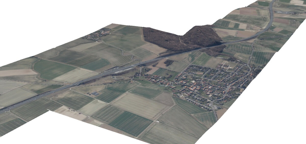
Once all the steps described are completed, there are a variety of output options. We produce accurate 3D models with all defined elements in place and correctly georeferenced. Our models contain all the necessary data to be used throughout the production process. 3D models are also converted into high quality GIS data, allowing the creation of large scale models that can be supplemented with other GIS layers such as terrain or various types of maps. The generated geometry is also converted to 2D plans for more conventional use cases.
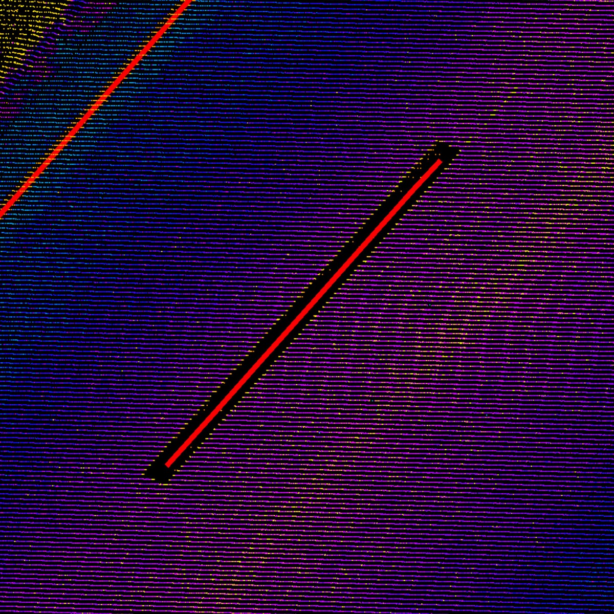 Other software
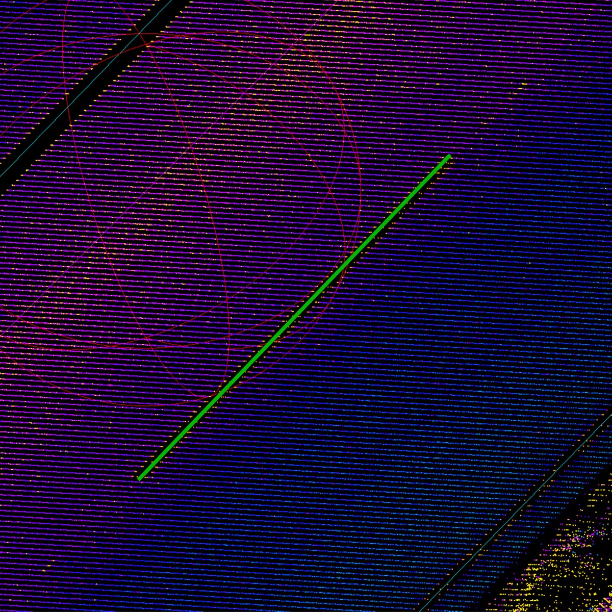 ioLabs Tools
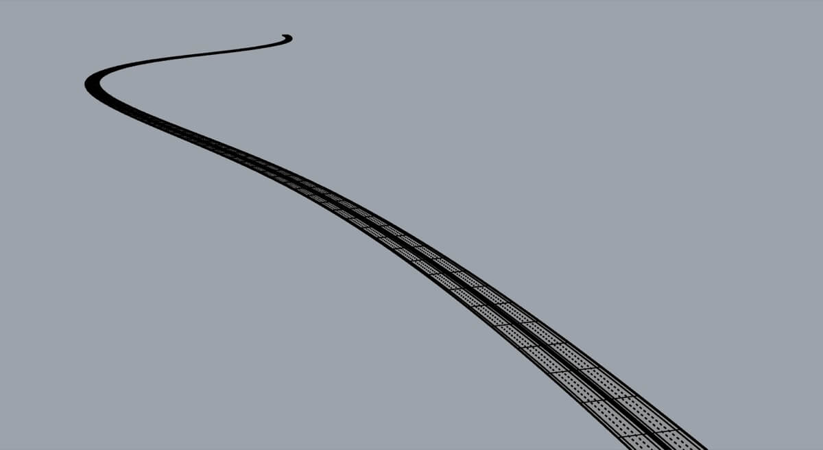
Since highways are very long continuous objects, processing such a large structure could be problematic. Our solution to this problem is to process the model incrementally. It is divided into short, performance-manageable sections that are processed one after the other. In this way, the total length of the highway structure model is practically unlimited, as it is always processed in separate parts and later merged together.
Conclusion
In this project we are working with very high precision and we managed to digitize the highway from scratch to final data models. We are able to collect precise 3D point data as a basis for this project and we managed to convert it into mathematical model. When we have a mathematical model, we are able to produce 3D file definition and generate 3D geometry itself. As a final product, we can produce data that can work within any BIM and GIS technology.
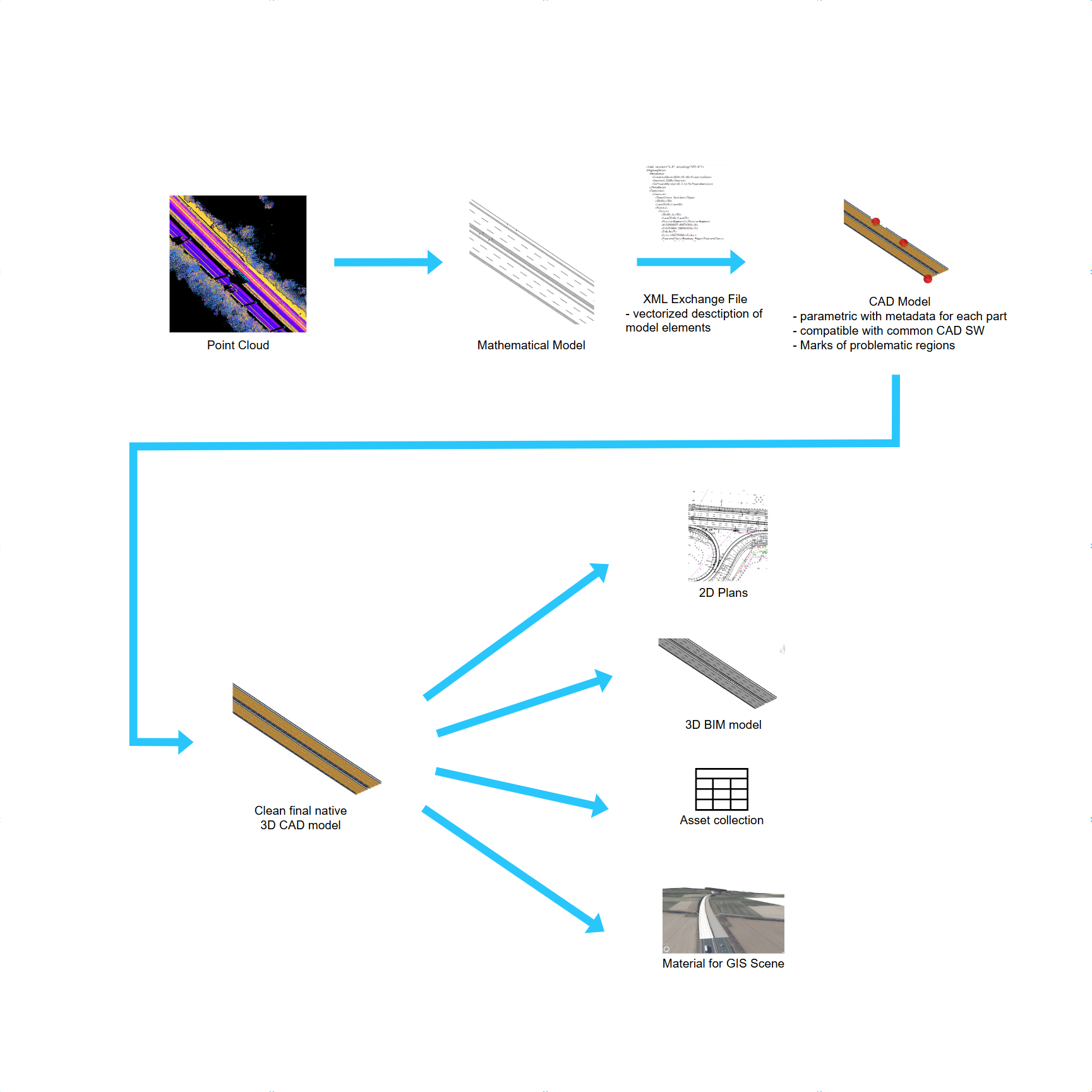
Raw point cloud data converted into mathematical model (by module 1). It is passed to Module 2 as an XML file containing vectorized description of model elements. Module 2 generates geometry elements with metadata in CAD file format. Result is available in multiple forms - CAD/BIM model, GIS model, 2D plans and markers of problematic regions as a source for feedback loop.
Project and Partner Website
Link to Project Website https://kirioll.com/
Link Vermessungsbüro Rink GbR: https://rink-vermessung.de/
Link Lang&Lang GmbH: https://www.service-lang.de/de/presseinformation
Credits
Vermessungsbüro Rink GbR
Lang&Lang GmbH
ioLabs AG
|
Technology
ioFramework
Python
ArcGIS Online
ArcGIS Pro
Open3D
Pytorch
Scipy
Rhinoceros
Audesk Revit
GEOgraf
Lidar 3D scanning
Drone 3D scanning
|

