The SecurityBIM workflow, developed under the leadership of SIEMENS, is a process that significantly accelerates the planning of security installations (e.g., alarm and surveillance systems). At the core of this workflow is the seamless placement of families in Autodesk Revit, which, once inserted into the drawing via drag and drop, can be automatically assigned to the corresponding rooms. These elements are easy to manage and can be extended with the required attributes, including metadata for cross-referencing. Based on this structure, various outputs can then be generated automatically – ranging from standard documents such as plan lists or legends to dynamic elements like cable overviews, bus overviews, central unit summaries, block diagrams, or standardized 2D plans. This substantially accelerates and simplifies the entire design process, allowing engineers to focus on their technical tasks rather than spending time on tedious routine activities.
Automatically generated sections
4
cable overviews, bus overviews, central unit summaries, block diagrams
Workload
2
hours to set up the example object shown in the video
Efficiency increase
70%
thanks to automation and a simple drag-and-drop process
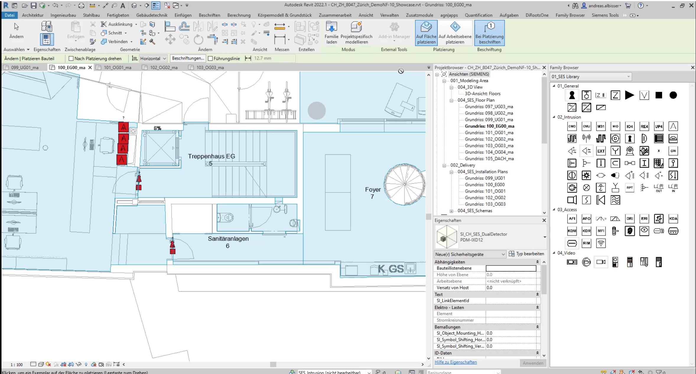
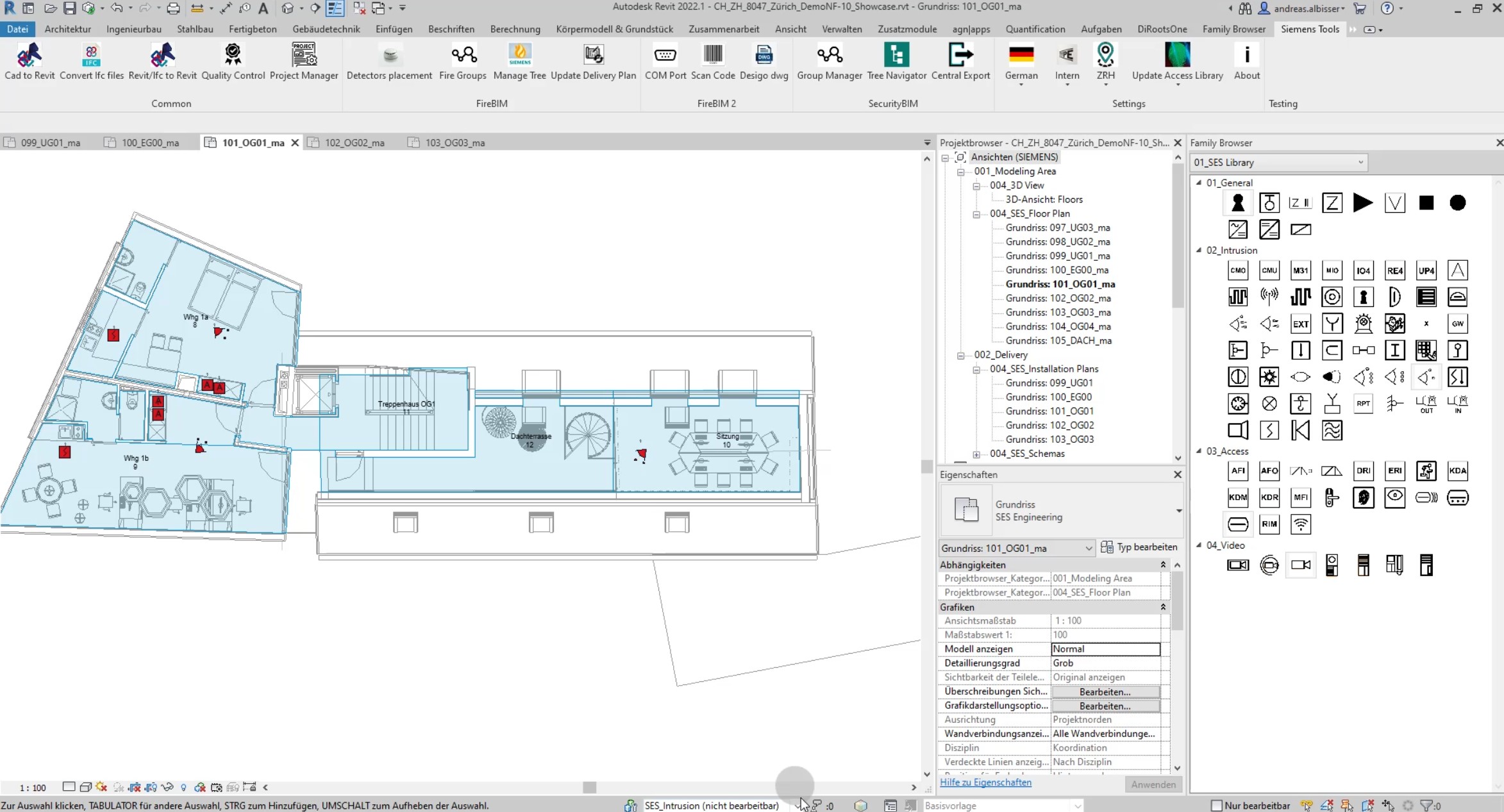
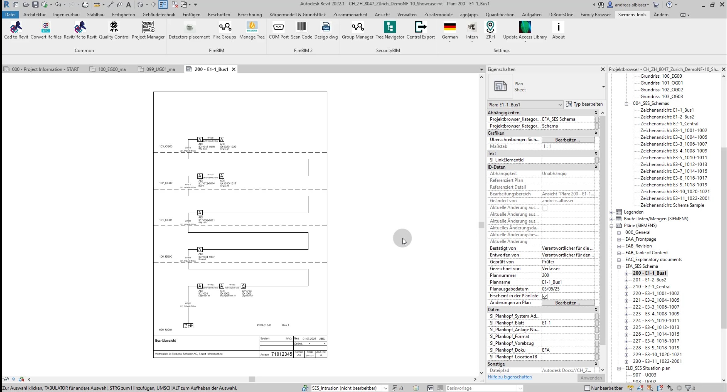
The workflow begins with the insertion of security components (families) into Autodesk Revit, which already contain all necessary attributes. Adding them to the project is done by simply dragging them from the library via the Family Browser or the Revit Project Browser. Each family is designed so that its 2D symbol matches the 3D model, allowing for combined work and further customization.
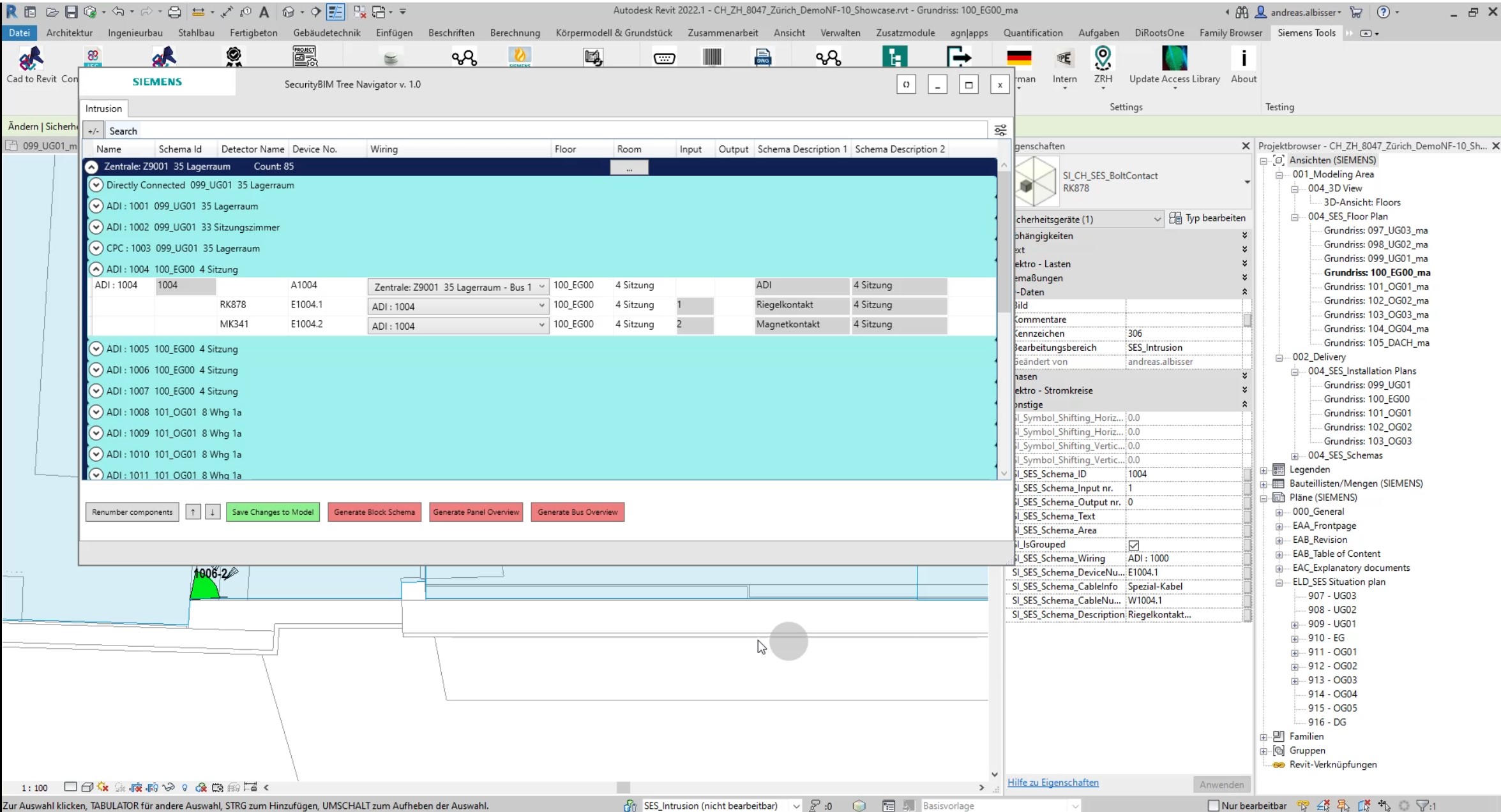
Once placed in the model, these elements can be grouped (i.e. linked), numbered, and arranged into a hierarchy and sequence. Attribute management – such as for IP addresses or element IDs – is simplified because most information is inherited directly from the families and can be centrally edited via the plugin interface.
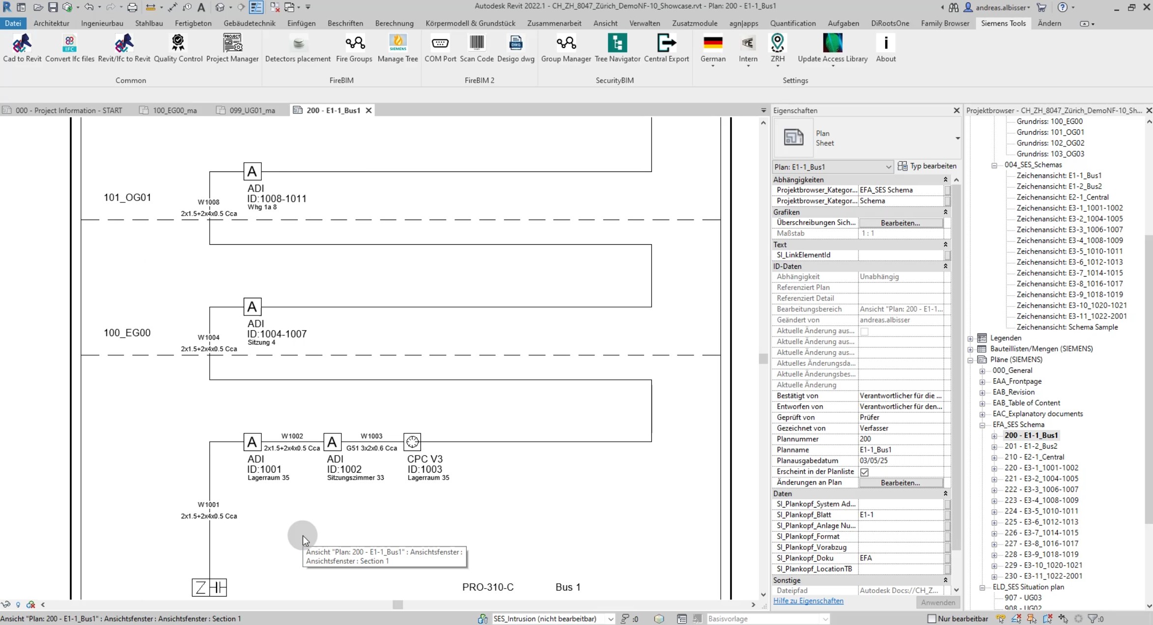
From these placed objects, various schematics can then be generated automatically, including bus overviews, central unit overviews, block diagrams, and standardized 2D plans.
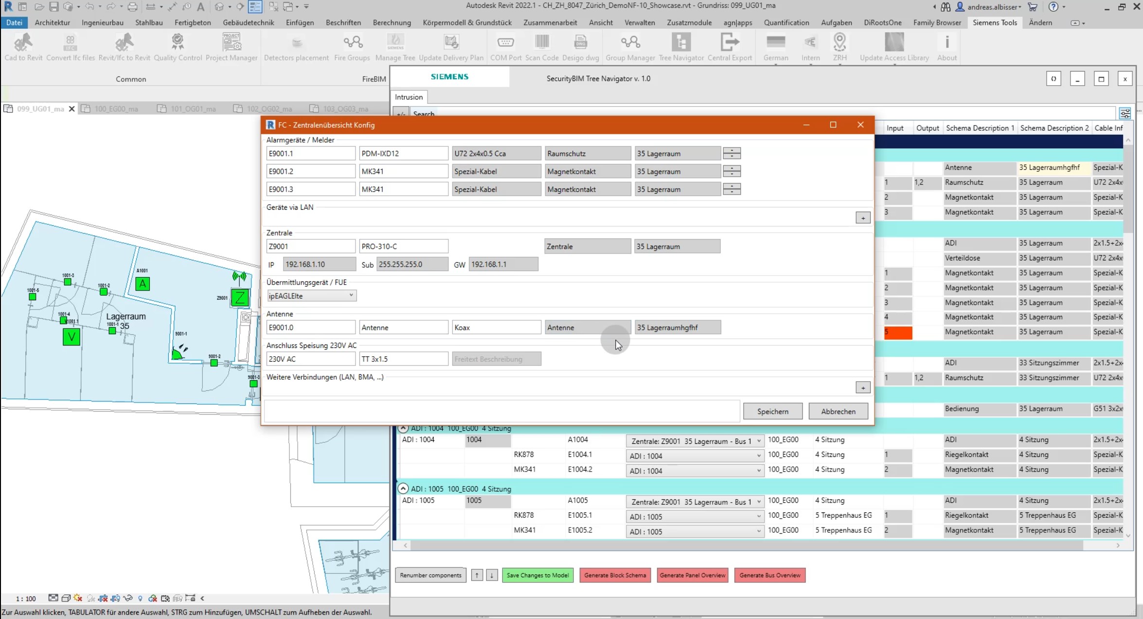
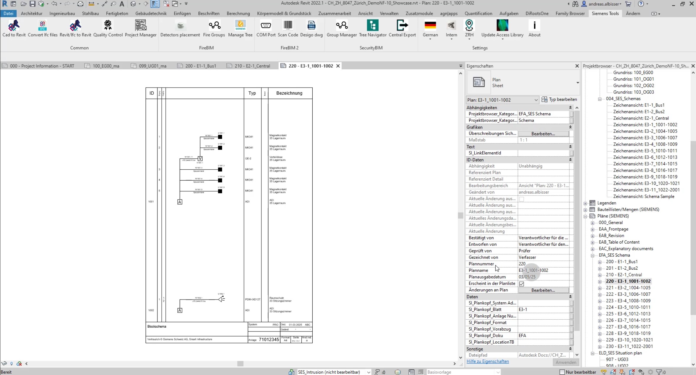
The bus overview lists all relevant (bus) devices in a clear sequence, starting with the central unit and broken down by floors. Each element includes detailed information (e.g. ID and associated room label). The central unit overview shows the central unit with detailed specifications, the connected devices (including type and label), and external connections with the appropriate cables. The block diagram displays all bus components with their associated devices (e.g. detectors), including type labels, description texts, and cable labels.
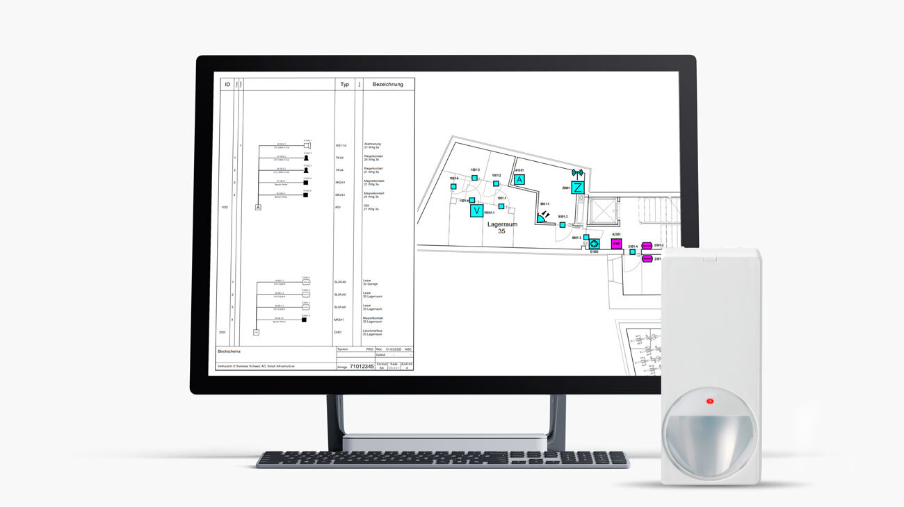
Consistent layout plans with placed detectors are presented uniformly using view templates. Together with accompanying documents, the generated content and layout plans are compiled into a complete execution documentation. This approach significantly simplifies the creation of project documentation, minimizes routine tasks, and saves both time and engineering resources.
Client
SIEMENS Schweiz AG
Credits
SIEMENS Schweiz AG
ioLabs AG
|
Technology
Revit API
C#
|